
Motor Mounts for an Electric Go-Kart
Converting a race go-kart from ICE to electric required redesigning the powertrain system to accommodate an AC induction motor. Aluminum (6061 T-6) motor mounts were developed to position the motor behind the rear axle, while providing the required structural support to account for dynamic loading and upwards of 44 ft⋅lbs of torque.
The Relectric go-kart build replaces an internal combustion engine (ICE) with a brushless AC induction motor (HPEVS’ AC-9) controlled by a Curtis motor controller. To simplify integration, the powertrain is designed to reuse the chain drive system which provides power transmission to the kart’s solid rear axle. The original gas engine was located to the right of the driver seat; however, the new motor is placed behind the rear axle to better accommodate the spatial demands of the battery systems and allow for an even weight distribution between the left and right side of the vehicle.
Motor Mounts

An adaptive mounting plate and a clamp were designed to integrate the motor with the frame of the kart. The main mounting plate has a recessed surface to accommodate the motor’s alignment ring, four bolt holes to attach the plate to the motor, and 2 bolt holes to mount the plate to the kart frame. The clamp mount is a two-piece system consisting of a top cap and a threaded base that tighten together to secure the back end of the motor. This helps support the weight of the motor and protects the main mounting plate from the moment produced by the high chain tension during acceleration. A rendering of the full motor mount assembly can be seen below.


Design for Manufacturing
Both the mounting plate and the clamp are manufactured from 1/2” thick Aluminum 6061. This material was selected as it has a higher strength to weight ratio and greater resistance to corrosion compared to steel. This reduces the need for powder coating protection.
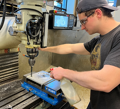
Manufacturing was completed in-house using a 3-axis CNC milling machine and a drill press. Throughout the design process, my team worked closely with the machinists to consider the cost efficiency and ease of manufacturing of our designs. While complex geometries may reduce the weight of the mounts, the designs were kept simple as the associated tooling time and monetary costs greatly outweighed the marginal decrease in the vehicles net weight. The photo below shows the mounts at the last stage before completion.

Fasteners
To minimize the potential for failure of the fasteners, the bolts and washers selected for this application were Grade 8 Steel with yellow zinc coating. These provide high tensile strength while offering resistance to corrosion. Since the motor mounting plates are aluminum, it is important that galvanic reactions between the fastener and motor mounts are minimized.
The preload and torque specs for the bolts are shown below and were calculated using a safety factor of 3 (a commonly used factor of safety in the automotive industry).

Final Results
Bolting up the motor assembly for the first time was a very satisfying experience. Since the motor mounting plates and the chassis are dissimilar metals, the chassis was painted to reduced potential chemical reactions between the two surfaces. Once the motor was mounted, we were able to start bench top testing the motor.


(Click for audio)